
Table of Contents
This tutorial is for geeks who want to learn a bit more about their BIOS and USB mass storage device booting. It describes how to use the test files in the TESTMBR folder of the full download of RMPrepUSB.
It refers to only the TESTMBR version that is in RMPrepUSB v2.1.617 and later only. The previous version was different! Source code for TESTMBR is also included with the RMPrepUSB download.
I will assume that you are interested in this article because you have one particular system that will not boot from your USB drive (and most other systems will) – so you want to investigate why this weird system of yours will not boot.
I will start with describing how to make a test USB drive and how you can test your BIOS. Later, I will describe how to interpret the results.
STEP 1 – HOW TO MAKE A ‘TEST PEN DRIVE’
Note: This will – of course – destroy all data on your USB drive!
- Download RMPrepUSB (full version)
- Select a USB pen drive (or USB hard disk) and insert it into your Windows computer (any computer will do – not necessarily the target computer you wish to test)
- Partition and format the drive as you intend to use it (you need to know where the PBR was placed – for instance if you use RMPrepUSB+HDD setting, the Partition Boot Record (PBR) will be placed at LBA 63).
- Select the drive in the drive selection list and click on File->Drive in the RMPrepUSB utility
- Choose one of the 5 BIN files from the RMPrepUSB\TESTMBR folder. If in doubt use one of the 32S files.
- Choose File Start = 0 (default)
- Choose USB SECTOR START = 0 (default)
- Choose LENGTH = 0 (default)
- Click OK to proceed
- Click the EJECT DRIVE button and remove the USB drive
You will need to repeat this for all 5 images in the order shown below. Some BIOSes give different results depending on what partitions are present, so apply an image, boot it, then apply the next image and boot that, etc, until you have tested with all 5 images.
The 5 BIN files (in order) are:
MBR0P.BIN – Debug MBR with no (i.e. an empty) partition table
MBR1P32S.BIN – Debug MBR with 1 entry in the partition table which has 32 sectors per track geometry (file is 31 sectors in size)
MBR2P32S.BIN – Debug MBR with 2 entries in the partition table which has 32 sectors per track geometry (file is 31 sectors in size)
MBR1P63S.BIN – Debug MBR with 1 entry in the partition table which has 63 sectors per track geometry (file is 63 sectors in size)
MBR2P63S.BIN – Debug MBR with 2 entries in the partition table which has 63 sectors per track geometry (file is 63 sectors in size)
The MBRxP32S files are 16384 bytes in size and will overwrite blocks 0-31 (sectors 1-32)
The MBRxP63S files are 32256 bytes in size and will overwrite blocks 0-62 (sectors 1-63)
Thus the PBR (partition boot record) will be left untouched if you choose the correct file. To check this you can use the USB Info button on RMPrepUSB and enter P1 for the start of the first partition. It should display the Partition Boot Record (aka Volume Boot Record or VBR) at sector xx. If in doubt use the 32S BIN files as these will not overwrite your PBR.
Q. Why have different BIN files and why do I need to format the USB drive in different ways?
A. When a BIOS detects a USB drive, it will interrogate the drive to try to determine how to treat the device (i.e. should it pretend it is a floppy drive or a ZIP drive or a hard disk, how many sectors per track and heads per cylinder does it have). So it matters how you partition and format the USB drive. For instance, if you format a USB drive which has no MBR or partition table, the BIOS may decide to treat it as a floppy drive. If you partition and format the same USB drive with an MBR and partition table containing a single partition entry, it may decide to treat the USB drive as a ZIP drive. If you partition and format the same USB drive with an MBR which contains two valid partition table entries, the BIOS may treat the USB drive as a hard disk. It is known that BIOSes do look at the contents of the first sector of the drive to try to determine what kind of device it is. It is also possible that some BIOSes may even look at the PBR active partition as well as the MBR to try to determine how to map the USB drive – for instance, if the PBR contained a BIOS Parameter Block (BPB) that held floppy disk values, the BIOS could decide to treat the USB drive as a ZIP drive instead of a hard disk drive. It is also known that a BIOS can treat a 256MB USB drive as a floppy drive, but a 512MB USB drive (that contains IDENTICAL contents), as a hard drive (the BIOS interrogates the USB drive for it’s physical drive size and from the size returned it determines how it should map the drive). For this reason you should try these different combinations and then record the results each time:
- CLEAN the USB drive and then overwrite with MBR0P.BIN
- Format the USB drive as MSDOS with no Overrides ticked and overwrite with MBR1P63S.BIN
- Format the USB drive as MSDOS with no Overrides ticked and overwrite with MBR2P63S.BIN
- Format the USB drive as MSDOS with use 64hd/32sec and overwrite with MBR1P32S.BIN (use a 512MB size for the partition or less)
- Format the USB drive as MSDOS with use 64hd/32sec and overwrite with MBR2P32S.BIN (use a 512MB size for the partition or less)
If possible use different drive sizes – a 256MB USB drive, a 512MB USB drive, a 1GB USB drive and a 2GB+ USB drive in each of these different test formats to determine if your BIOS also uses the USB drive capacity to determine how to boot the drive. For instance some older Intel BIOSes will not boot from any USB drive if it is larger than 256MB (i.e. it will not even read the first sector into memory and execute the MBR code, if the physical capacity of the drive is over 256MB when first interrogated during BIOS POST). Typically these types of older BIOSes boot low capacity USB drives as ZIP (large floppy) drives.
Intro (skip this bit if you know this stuff already and go to Step 2!)
Before a BIOS loads the data (code) from the first sector of a USB drive and runs that code, it has to decide how to ‘map’ that device to the standard int 13h BIOS call that all boot code uses. If the BIOS decides that the USB device is a floppy device, the BIOS will respond to ‘floppy drive’ int 13h requests (i.e. DL=00). If the BIOS treats the device as a hard disk type, it will respond to ‘hard disk’ int 13h requests (DL=80h). If the BIOS treats the USB device as a ZIP device, it will respond to access requests as a floppy (DL=00) but it will translate any request such that a request for Sector 1 (LBA0) will return the PBR of the device, a request for Sector 2 will return the sector after the PBR and so on. Thus to any real-mode (DOS) OS, the USB ZIP device will appear to be just like a big floppy disk with no MBR or reserved sectors.
There is no standard for how a BIOS should ‘decide’ on how to map a USB device. Different BIOSes use different decision trees. Some do not even bother and just assume all USB storage devices are of one type (e.g. HDD). Some older BIOSes assume all USB device are ZIP devices if they are over 1.44MB in size – otherwise FDD. Some only do the ZIP translation/adjustment if you use Int13h Standard CHS calls but do not translate sector addresses if you call the Extended Int13h interrupt routines!
Another thing the BIOS has to decide is what to do when the OS requests a ‘read’ or ‘write’ from Cylinder 5, Head 1, Sector 1 on the UFD using the standard Int 13h 02/03 calls. The UFD has no real heads or cylinders! So the BIOS has to translate this CHS ‘address’ into a Logical Block Address (LBA). But how does it know how many sectors are in a track (SPT) or how many tracks are in a cylinder (HPC)? One common method is to look at the Ending Head and Sector values in the partition table of the MBR. As (until Vista) all partitions ended at the end of a whole cylinder, the End Head value shows how many heads there are per cylinder, and the End Sector value shows how many sectors there are per track. The BIOS can then use these values to calculate an LBA address when the OS asks for CHS address 5 1 1. Unfortunately, other BIOSes just assume 63 SPT and 255 HPC. This is especially true of modern BIOSes because Vista and Win 7 Diskpart creates partitions at any start address and any end address now and does not adhere to the old DOS/Win98/XP ‘rule’ of starting partitions at the start of a track and ending partitions at the end of a cylinder. The Sectors per Track and Heads per Cylinder count is called the ‘drive geometry’ and can cause a lot of issues. It was quite common for some older BIOSes to default to 240 Heads per Cylinder as a maximum value.
Because when the int 13h disk call was first introduced on the IBM PC, the software engineers did not imagine you could have a disk larger than 500MB (that would be crazy!), they designed the int 13h interface to only go up to a maximum of 1024 cylinder by 16 heads (how can a disk drive possibly have more than 16 heads?) by 63 sectors per track. As disk sizes grew and disk became intelligent, the int 13h ‘standard’ had to be redefined. Each time it was redefined, the BIOS had to be changed and some were changed better than others! When disk drives reached over 8GB, the Extended Int 13h interface had to be developed and now even that is not good enough to handle modern drives over 2TiB (though 4TiB disks are just possible as long as the last partition starts below the 2TiB limit!). The whole thing is such a fiasco that it is a wonder disks boot at all! See here for more info.
To find out more about Int 13h – see here and here. For BIOS software-invoked interrupts see here.
Step 2 – Using the test USB drive on your problem system
IMPORTANT: You must follow these instruction exactly and you must make a note of all settings (even if you think you can remember afterwards!).
- Note down the BIN file that you just used and how it was pre-formatted in RMPrepUSB
- Switch off the target system (Yes – I really mean it – not CTRL-ALT-DEL – switch it off every time – we need this to be repeatable!)
- Insert your test pen drive into the target system
- Switch on the target computer, go into the BIOS menu and set any USB settings as required and make a note of these settings. As well as boot order (which you need to set to boot the USB pen drive first), there may be settings for ‘USB type = Fixed/Removable’, USB Auto Size = xxxMB, USB Boot type=USB-FDD/USB-ZIP/USB-HDD, etc. If there is more than one possibility, you will need to test each in turn. Note that some BIOSes may list your USB drive as USB KEY: ACME xxxx (F) and other times list the same USB key as USB KEY: ACME xxxx (H) – the (F) indicates the BIOS has mapped the USB device as a floppy and the (H) indicates it has mapped it as a Hard disk. The BIOS will decide which way to map the USB pen depending on how it has been formatted. Also note that a CTRL-ALT-DEL warm reboot may not change this mapping even if you have reformatted the USB drive in a completely different way – this is why I say to always SWITCH OFF your system before you test a USB drive for bootability every time you format it.
Allow the target computer to boot from the test pen drive – you should briefly see ‘R’ and then a screen like this:
This shows the expected correct result for a UFD which has booted as a hard disk (63 SPT, 32 Heads per Cyl)
Repeat the test using a different BIN file. You can also re-format in step 1.3 using a different option (e.g. MSDOS or XP or Win7 PBR, 64/32 or 255/63, ZIP or HDD).
STEP 3 – INTERPRETING THE RESULTS
Using the table below, you can see that in this example, the USB pen was treated by the BIOS as a hard disk (80=Hard disk). An extended int 13h BIOS call was made to read sector 1 (LBA0) and the correct sector was returned by the BIOS. A standard int 13h CHS call to read sector 1 (LBA0) also returned the correct sector. We could therefore expect this BIOS+BIOS Setting+USB pen+partition table data to boot as a standard hard disk.
Text Displayed Meaning
————– ————————————————————————————————————
R MBR code is Running – about to relocate to 0:600h in memory)
<Clear Screen> R is cleared after relocation
xx where xx is the BIOS drive number, 80h is the first hard disk, 00h is the first floppy
aaaa bbbb cccc dddd AX, DX and CX returned by get disk geometry AH=8 call – see below for explanation
L denotes LBA extended Int 13h calls are supported and LBA 0 is about to be read
l denotes the LBA extended Int 13h call FAILED!
S denotes a Standard CHS Int 13h call – sector 1 is about to be read
s denotes Standard CHS call FAILED!
<type> where HDD0 means hard disk type, FDD0 means floppy disk type,
Zxx denotes the BIOS booted a different sector than LBA0)
The sector LBA address is printed after this if it was recognised
?<hex string> denotes that the sector returned was not one of those in the MBRxxx.BIN image
– the first 16 bytes of the sector are displayed.
If the sector is the PBR and the disk type is FDD0
then the drive will boot as a USB-ZIP drive and appear as drive A: to DOS).
For a USB key that boots as a floppy, expect 00 and ‘FDD0’ to be displayed
For a USB key that boots as a super-floppy/ZIP drive expect 00 and ? and the first 16 PBR bytes to be displayed
For a USB key that boots as a hard disk, expect 80 and ‘HDD0’ to be displayed
If HDD & Z or FDD & Z or ? followed by non-PBR bytes is displayed then you have a strange BIOS indeed!
aaaa bbbb cccc dddd – e.g. 0000 1F02 003F 03B3 = AX DX CX_sector CX_cylinder
These are the values returned after calling the Get Disk Geometry call (int 13h AH=8) – and can be interpreted as follows:
AX=0000– This should always be 00?? for no error – if not then the BIOS error number is held in the first two hex characters (xx00).
DX=1F02 – This is actually two groups of numbers or fields – HH=1F + DD=02 – where HH is the last head number = 1F = 31 which therefore means 32 heads, and DD is 02 = number of disks seen by the BIOS (if HDD is printed then this means 2 hard disks are seen by the BIOS, the USB flash drive and the hard disk in the system, for instance. If FDD is printed, then this is the number of floppy drives seen by the BIOS)
CX_Sector=003F – last sector number = 63, so 63 sectors per track (as sector numbers start from 1)
CX_cylinder=03B3 – last cylinder number = 947, so disk has 948 cylinders (as cylinder numbers start from 0)
If your MBR has 63/255 geometry, but the BIOS TESTMBR result shows the BIOS is using 64/32 geometry, it may boot if you use RMPrepUSB and tick the 64/32 checkbox when formatting this type of USB drive and using it on this BIOS.
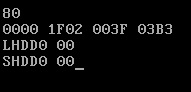
Another example:
USB-FDD with MBR1P32S.BIN booted on Asus EeePC 904HD
80
0000 0103 0012 013C
LHDD0 00
SHDD0 00
This shows the BIOS has assumed 2 heads and 18 sectors per track (and ignored the partition table values in the MBR) and 317 cylinders. The 80 shows that the BIOS has mapped it as a hard disk (despite the USB device identifying itself as a floppy drive!). It shows 3 hard disks present as the USB device also has an HDD device on the controller (a 1GB USB Disk Pro). The HDD0 00 messages show that the BIOS is not translating sector addresses and so is not in ZIP mode. If any boot code or OS was placed on this drive, it may have problems. It would be best to use a non-MBR image with no partition table on this USB-FDD part of the drive.
Tip: To copy the TESTMBR BIN files onto a USB-FDD device (e.g. Netac U207, Disk Pro, etc.), use dd.exe v0.5 for Windows by John Newbigin:
dd –list (to find floppy device or hdd device ID)
dd of=\\?\Device\Floppy0 if=MBR1P32S.BIN
You can also use dd on a physical USB drive after –list to find out it’s designation under Windows – e.g. \\?\Device\HardDisk1\DR29 (but RMPrepUSB File->Drive and Drive->File is much safer!).
If you format a UFD using RMPrepUSB as USB-ZIP + FREEDOS, then the FreeDos PBR will be changed so that it has floppy drive parameters – therefore it may not boot if your BIOS maps it as a hard disk (80) instead of a floppy (00). So you should format the UFD as USB-HDD. Some BIOSes work better if you use 63/255 geometry and some if you use 64/32 geometry.
Generally, if a BIOS maps a UFD as a hard disk, then use 63/255 geometry.
If you need to boot as a floppy (A:) then see the grub4dos tutorial examples for some methods to ‘convert’ a UFD that boots as a hard disk but can make it appear to the OS (DOS) as a floppy drive.
STEP 4 – USING GRUB4DOS
If you can see nothing wrong with the results returned by the TESTMBR code, you can try installing grub4dos. Use RMPrepUSB and click the ‘Install grub4dos’ button (after correctly re-formatting the USB drive using RMPrepUSB – of course). All you need on the USB drive is the grldr file which RMPrepUSB will copy across for you automatically. Now try to boot from the USB drive and you should get to a grub4dos command ‘shell’. Once in this command shell, you can use some grub4dos commands to see how the drive has been mapped.
First type ‘geometry’ (you can type ge and hit the <TAB KEY> and grub4dos will fill in the rest of the command)
Next type map ( then hit the <TAB KEY> – grub4dos will show you what drives it thinks are present – rd is ramdrive and can be ignored as it is created by grub4dos
Now try ls / to list files on the current device (which should be your boot drive)
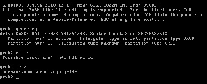
Notice that the geometry command shows how the USB drive appears to an OS with 64 heads, 32 sectors per track and 991 cylinders. It has two partitions (a dummy type 21 was created by RMPrepUSB USB-HDD option to try to force the BIOS to treat the UFD as a hard disk).
Tip: Sometimes using the command geometry –tune can change the BIOS drive CHS geometry. This command may be useful to include in your grub4dos menus.